Unregulated Power Supply
This page come from ww.zen22142.zen.co.uk, show you about circuit of un regulated powersupply:A basic full wave rectified power supply is shown below. The transformer is chosen according to the desired load. For example, if the load requires 12V at 1amp current, then a 12V, 1 amp rated transformer would do. However, when designing power supplies or most electronic circuits, you should always plan for a worst case scenario. With this in mind, for a load current of 1 amp a wise choice would be a transformer with a secondary current rating of 1.5 amp or even 2 amps. Allowing for a load of 50% higher than the needed value is a good rule of thumb. The primary winding is always matched to the value of the local electricity supply.

Notes:
An approximate formula for determining the amount of ripple on an unregulated supply is:
Vrip = Iload * 0.007 / C
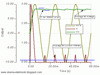
where I load is the DC current measured through the load in amps and C is the value of the capacitor in uF.The diagram below shows an example with a load current of 0.1 amp and a smoothing capacitor value of 1000uF.
The calculated value of ripple is (0.1 * 0.007) / 1000e-6 = 0.7 volts or 700mV. The value of peak-peak ripple measured from the graph is 628mV. Therefor, the equation is a good rule of thumb guide for choosing the correct value for a smoothing capacitor in a power supply.


