


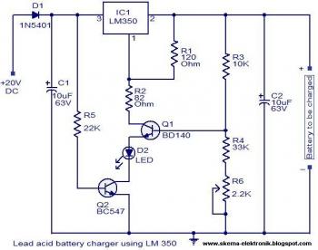
Simple Battery Charger using LM350
The schematic diagram can be used for charging the 12V lead acid batteries. The circuit is designed as a constant voltage source with a negative temperature coefficient. The transistor Q1 (BD 140) is used as the temperature sensor. The transistor Q2 is used to prevent the battery from discharging through R1 when the mains power is not available. The circuit is designed based on the voltage regulator IC LM350. The output voltage of the charger can be adjusted between 13-15 V by varying the POT R6.The LM350 will try to keep the voltage drop between its input pin and the output pin at a constant value of 1.25V. So there will be a constant current flow through the resistor R1. Q1 act here as a temperature sensor with the help of components R6/R3/R4 which more or less control the base current of Q1. As the emitter/base connection of transitor Q1, just like any other semiconductor, contains a temperature coefficient of -2mV/°C, the output voltage will also show a negative temperature coefficient. That one is only a factor of 4 larger, because of the variation of the emitter/basis of Q1 multiplied by the division factor of P1/R3/R4. This results in approximately -8mV/°C. The LED will glow whenever the mains power is available.
The transistor Q1 must be placed as close as possible to the battery.
Use a 20 to 30 V / 3A DC power supply for powering the circuit.
This circuit is not possible for charging GEL type batteries as it draw large amounts of current.


