


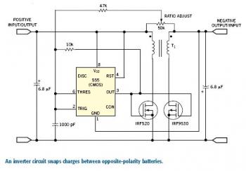
Bidirectional Power Inverter
If you want to swap charge in either direction between unevenly loaded positive and negative battery buses, you need an inverting dc transformer. One implementation is the symmetrical flyback converter shown in Figure 1. The circuit can generate a negative output from a positive supply or a positive output from a negative supply. When the circuit starts up, the substrate diode of the output FET bootstraps the output voltage to the point where synchronous switching takes over. When the gate-switching signal is symmetrical, the output voltage is approximately -95% of the input voltage, and the efficiency is greater than 80%. You can obtain voltage step-up or step-down by adjusting the switching ratio.When I used the circuit between two 4V lead-acid batteries, a comparator adjusted the switch ratio to drive charge in the desired direction. The circuit automatically replaces charge drained from one battery to the other. In a short-battery-life application, the 2.5-mA standby current from each battery may be negligible. Using lower-gate-capacitance, FETs can reduce losses. Alternatively, you can add gates to the drive circuit to turn off both FETs whenever the battery voltages balance. The minimum input voltage is a function of the gate thresholds of the FETs. The ±9V rating of the CMOS 555 timer sets the maximum voltage. My prototype supplies approximately 100 mA.


